
The difference between safety valves and pressure reducing valves
author: 003
2026-09-02
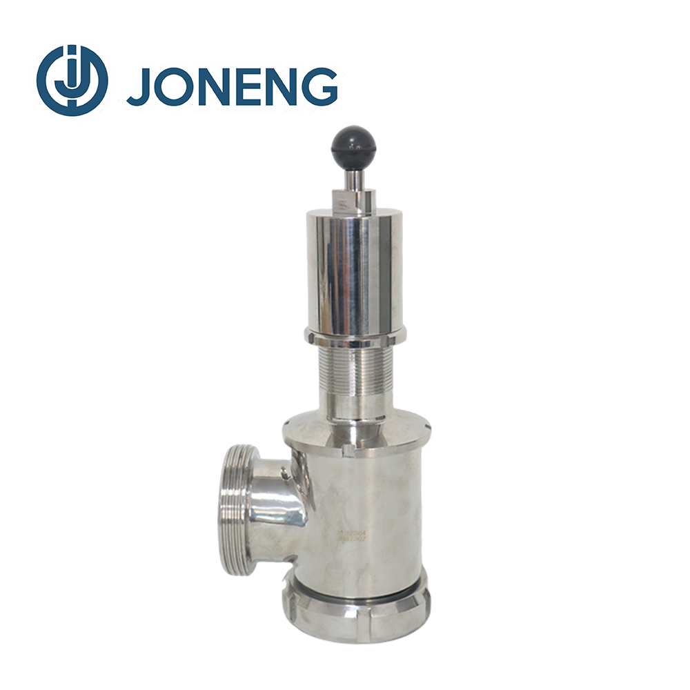
The difference between safety valves and pressure reducing valves
In fluid piping systems, pressure management is a crucial aspect of ensuring the reliable operation of the entire system. Safety valves and pressure reducing valves may appear similar, as both are valve components designed to manage pressure. Many novice users easily confuse the two, even using them interchangeably. However, they actually address two completely different problems: one serves the daily operation of equipment, while the other handles the risk of sudden failures.
I. Core Mission: Active voltage regulation to adapt to operating conditions VS Passive protection against over-limits
Pressure Reducing Valve: Modifying Input Pressure to Ensure Normal Equipment Operation Many pipelines experience unstable upstream pressure, fluctuating wildly with changes in upstream supply. Downstream equipment and piping components can only operate stably under a fixed pressure range. The pressure reducing valve's role is pressure conversion; it continuously lowers and stabilizes the high, fluctuating upstream pressure to the target pressure required by the equipment. As long as the system is running, the pressure reducing valve is constantly regulating. It is designed for normal system operation, aiming to provide downstream equipment with continuous, stable, and compliant pressure conditions, allowing the entire system to smoothly complete its daily operations.
Safety Valve: Not Interfering with Normal Operation, Only Handling Overpressure Faults
Safety valves do not actively change the daily operating pressure of the pipeline. When the entire system is operating normally and the pressure remains within the design range, the safety valve remains fully closed and does not participate in any pipeline pressure regulation. Only when the system experiences an abnormal fault, and the internal pressure rises uncontrollably, approaching the pressure limit that the pipeline or cavity can withstand, will the safety valve intervene. It is designed for unexpected failure scenarios and serves as a backup safety barrier for the entire system. Its purpose is not to optimize equipment performance, but to avoid various damage problems caused by excessive pressure.
Safety valves do not actively change the daily operating pressure of the pipeline. When the entire system is operating normally and the pressure remains within the design range, the safety valve remains fully closed and does not participate in any pipeline pressure regulation. Only when the system experiences an abnormal fault, and the internal pressure rises uncontrollably, approaching the pressure limit that the pipeline or cavity can withstand, will the safety valve intervene. It is designed for unexpected failure scenarios and serves as a backup safety barrier for the entire system. Its purpose is not to optimize equipment performance, but to avoid various damage problems caused by excessive pressure.
II. Logic of Medium Path and Flow Direction
Pressure reducing valve: The medium flows completely through the valve body and is connected in series in the main pipeline. The pressure reducing valve is an essential component of the main pipeline, ensuring the fluid medium passes completely through the valve body. The medium flows into the valve body from the inlet, and after the valve core adjusts the opening, it flows out from the outlet to the downstream pipeline and equipment. The inlet connects to the upstream with unstable pressure, and the outlet connects to the downstream end of the entire system. The medium continuously flows through the valve. It is a functional element connected in series in the main process flow; pipelines must pass through the pressure reducing valve to transport the medium.
Safety valve: The medium does not flow to downstream equipment; it is a branch discharge. The inlet of the safety valve connects to the pressurized pipeline or cavity, but its outlet does not connect to the next section of the process pipeline. Only in the event of overpressure triggering does the medium enter from the valve body inlet and be directly discharged from the outlet, preventing it from being transported to downstream equipment. It is not connected in series in the main medium transport pipeline but is installed as a branch at the pressure point, acting as a bypass protection accessory. No medium flows through it during normal operation.
Safety valve: The medium does not flow to downstream equipment; it is a branch discharge. The inlet of the safety valve connects to the pressurized pipeline or cavity, but its outlet does not connect to the next section of the process pipeline. Only in the event of overpressure triggering does the medium enter from the valve body inlet and be directly discharged from the outlet, preventing it from being transported to downstream equipment. It is not connected in series in the main medium transport pipeline but is installed as a branch at the pressure point, acting as a bypass protection accessory. No medium flows through it during normal operation.
III. The Practical Significance of Pressure Setting
Pressure reducing valve setpoint = System daily operating pressure
The pressure value we set for the pressure reducing valve is the daily operating pressure used by the downstream equipment. For example, if the equipment requires 4 bar to operate, the pressure reducing valve is set to 4 bar. Regardless of slight increases or decreases in upstream pressure, the goal of the pressure reducing valve is to ensure that the downstream pressure remains stable at 4 bar. This setpoint is the standard parameter for normal system operation.
Safety valve setpoint = System's maximum permissible pressure limit
The safety valve's setpoint pressure must be higher than the equipment's normal operating pressure. The equipment's normal operating pressure must never approach or reach the safety valve's setpoint. For example, if the equipment's normal operating pressure is 4 bar, the safety valve's setpoint is generally 7-8 bar. Only in case of a malfunction and pressure exceeding this 7-8 bar safety threshold will the safety valve activate. This setting represents a "precautionary line that cannot be exceeded," not the daily operating pressure.
The pressure value we set for the pressure reducing valve is the daily operating pressure used by the downstream equipment. For example, if the equipment requires 4 bar to operate, the pressure reducing valve is set to 4 bar. Regardless of slight increases or decreases in upstream pressure, the goal of the pressure reducing valve is to ensure that the downstream pressure remains stable at 4 bar. This setpoint is the standard parameter for normal system operation.
Safety valve setpoint = System's maximum permissible pressure limit
The safety valve's setpoint pressure must be higher than the equipment's normal operating pressure. The equipment's normal operating pressure must never approach or reach the safety valve's setpoint. For example, if the equipment's normal operating pressure is 4 bar, the safety valve's setpoint is generally 7-8 bar. Only in case of a malfunction and pressure exceeding this 7-8 bar safety threshold will the safety valve activate. This setting represents a "precautionary line that cannot be exceeded," not the daily operating pressure.
IV. Consequences of Valve Failure
Pressure reducing valve malfunction: Primarily causes abnormal operating conditions. When internal parts of a pressure reducing valve wear or seals are damaged, downstream pressure may remain high, be too low, or fluctuate significantly. This malfunction directly affects equipment performance, preventing it from reaching its ideal operating state. In most cases, pressure reducing valve failure does not immediately pose a sudden safety hazard; it is more of a production and usage issue.
Safety valve malfunction: Directly causes safety protection failure. Safety valve failure occurs in two ways. First, the valve core may be stuck shut, preventing the valve from opening and releasing pressure when the system is overpressured. This leads to a continuous accumulation of pressure in the pipeline and sealed chamber, increasing the risk of component damage. Second, the sealing surface may be damaged, preventing the valve from closing tightly and causing unauthorized leakage of the medium. Once a safety valve fails, the last line of pressure protection for the entire system disappears, significantly increasing potential risks.
Safety valve malfunction: Directly causes safety protection failure. Safety valve failure occurs in two ways. First, the valve core may be stuck shut, preventing the valve from opening and releasing pressure when the system is overpressured. This leads to a continuous accumulation of pressure in the pipeline and sealed chamber, increasing the risk of component damage. Second, the sealing surface may be damaged, preventing the valve from closing tightly and causing unauthorized leakage of the medium. Once a safety valve fails, the last line of pressure protection for the entire system disappears, significantly increasing potential risks.
Summarize
In short, their functions are as follows: pressure reducing valves address the issue of "unsuitable pressure preventing equipment from operating normally," serving daily production; safety valves address the issue of "complete pressure loss, preventing component damage," specifically handling sudden malfunctions. Their functions complement each other but are not interchangeable. In many complete piping systems, both are configured simultaneously: the pressure reducing valve adjusts the pressure to a suitable operating level, while the safety valve maintains the maximum safe pressure limit, jointly ensuring the stable and reliable operation of the entire pipeline.
Why do stainless steel valves and pipe fittings still rust? Isn't stainless steel supposed to be "rust-proof"?
Screw pump vs. cam rotor pump
Related Article

The sanitary butterfly valve is the most-specified valve in any hygienic plant — cheap, compact, fast and easy to clean. It is also the valve most often mis-specified, which is why a unit that "looked fine on paper" starts leaking after one CIP season. This guide covers the seven decisions that determine whether your butterfly valve holds up: seat material, connection and standard, actuation, torque sizing, finish and maintenance.
Sanitary Butterfly Valve Selection Guide: How to Specify a Hygienic Butterfly Valve

"Send us a 2-inch valve." Sounds simple — until the DIN line, the ISO line and the American line all turn out to have different outside diameters. Here is the comparison table our engineers use every day, and the five rules that prevent 90% of sanitary connection mistakes.
Sanitary Tube and Valve Standards Compared: DIN 11850, ISO 2037, SMS 3008, BS 4825 and ASME BPE

In hygienic plants, seals — not valve bodies — cause over 80% of valve service issues, and most of them announce themselves weeks in advance. This guide walks through the symptoms our service engineers meet most often, what each one really means, and the maintenance rhythm that keeps AB valves leak-free for years.
Sanitary AB Valve Troubleshooting: Leakage, Seal Failure and Sticking — Causes, Fixes and a Maintenance Schedule

Surface treatments fall into three categories: chemical (addressing corrosion resistance), mechanical (addressing appearance), and electrochemical (addressing both). When selecting a method, first consider three factors: the required level of corrosion resistance, the strictness of cleanliness standards, and the budget.
Differences in Surface Treatment Processes for Pipe Fittings and Selection Guidelines