
Installation guide for a threaded stainless steel check valve
author: 003
2026-07-18
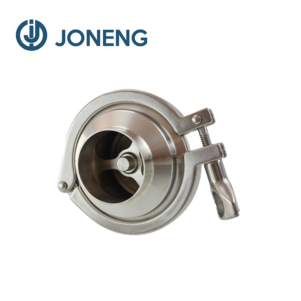
Installation guide for a threaded stainless steel check valve
I. Pre-installation Preparation and Inspection
Verify Valve Markings Match Operating Conditions
Material Confirmation: The valve body should have clear material markings (e.g., "316" or "CF8M") to ensure compatibility with the pipeline medium and prevent stress corrosion cracking. Especially in environments containing chloride ions, 304 stainless steel may not be suitable.
Pressure-Temperature Ratings: Threaded valves are mostly 2000/3000/6000 lbs. Verify the Class pressure value marked on the valve body and confirm the allowable pressure under actual operating conditions based on the stainless steel temperature-pressure curve. Do not select based on room temperature values directly.
Flow Direction Arrow: Check valves are one-way valves, and a flow direction arrow is cast on the valve body. It must be confirmed that the arrow direction is completely consistent with the flow direction of the pipeline medium; otherwise, the valve will not open or will fail to close.
Material Confirmation: The valve body should have clear material markings (e.g., "316" or "CF8M") to ensure compatibility with the pipeline medium and prevent stress corrosion cracking. Especially in environments containing chloride ions, 304 stainless steel may not be suitable.
Pressure-Temperature Ratings: Threaded valves are mostly 2000/3000/6000 lbs. Verify the Class pressure value marked on the valve body and confirm the allowable pressure under actual operating conditions based on the stainless steel temperature-pressure curve. Do not select based on room temperature values directly.
Flow Direction Arrow: Check valves are one-way valves, and a flow direction arrow is cast on the valve body. It must be confirmed that the arrow direction is completely consistent with the flow direction of the pipeline medium; otherwise, the valve will not open or will fail to close.
Valve Cleaning and Visual Inspection
Unpack the valve and use clean compressed air or a clean cloth to remove rust-preventive oil, chips, or packaging debris from the valve body cavity and threaded joints. High-pressure systems are sensitive to cleanliness; impurities may scratch the sealing surfaces.
Inspect the valve body and end threads for casting defects, cracks, or transportation damage. Manually push the valve disc (if it is a lift or spring-return type); it should move freely without jamming, the spring should make a clear sound, and there should be no permanent deformation.
Pipe End Thread Preparation: The pipe end thread must be a tapered pipe thread standard consistent with the valve (such as NPT, BSPT, RC, etc.), with NPT threads being the most common. Mixing different standards will cause leaks.
Re-thread using a good die or check with a thread gauge; the threads should be smooth, free of burrs, broken threads, or stripped threads. Damaged threads are a root cause of leaks.
II. Selection and Application of Sealing Materials
The sealing of threaded stainless steel check valves relies on thread engagement and sealant filling. The traditional method of using hemp fibers and thick white paint is absolutely prohibited, as hemp fibers absorb moisture and easily lead to corrosion of stainless steel gaps.
Recommended Sealing Materials:
PTFE Tape: The most universal. Select high-quality PTFE tape suitable for stainless steel (such as a nickel-based anti-seize formula), with a density not less than 1.0 g/cm³. Wrap in the same direction as the thread insertion (clockwise), generally 3-5 turns. Do not wrap too many turns to avoid squeezing into the valve cavity.
Anaerobic Pipe Sealant: High pressure and vibration resistant, completely fills gaps and cures to prevent loosening. When selecting, ensure compatibility with the medium and temperature, and that it does not shrink after curing. Apply evenly, covering 2/3 of the total thread length, leaving the first turn uncoated to prevent adhesive from entering the valve body.
Liquid PTFE Sealant: Suitable for precision systems requiring no debris. Note that stainless steel threads are "non-reactive metals," and some anaerobic sealants must be used in conjunction with an accelerator.
Key points for application: Apply to external threads (pipe end), not internal threads of the valve body, to prevent the sealant from being pushed into the valve seat area.
Install immediately after application to prevent the sealant from hardening on the surface and affecting the sealing effect.
III. Installation and Operation Procedures
**Manual Pre-tightening:** Screw the valve onto the pipe end thread, rotating it manually until you feel noticeable resistance (usually 3-5 turns). Ensure the valve end face and pipe end have a uniform gap; the threads are now initially aligned.
**Wrench Tightening:**
**Clamping Position:** The wrench must be tightened strictly onto the hexagonal or octagonal head of the valve end. Never clamp the middle of the valve body or the valve cover. The valve body is often made of precision casting or forging, and its wall thickness is insufficient to withstand the wrench torque, easily deforming and causing the valve disc to jam or break.
**Applying Torque:** Use an appropriately sized adjustable wrench or box wrench. From the "hand-tightened" position, tighten another 2-3 turns (refer to the manufacturer's instructions) until the thread sealing surface undergoes slight elastic deformation to achieve metal-to-metal contact. For NPT threads, the standard tightening turns are: after hand-tightening, 1.5-2 turns for valves with a diameter of 10mm or less, and 2-2.5 turns for valves with a diameter of 10-25mm. If the valve is not tight enough, it will leak; if it is too tight, the valve body end will crack.
Stress-free installation: Ensure the valve is concentric with the opposite pipe; do not forcibly correct misalignment using threads. Assembly stress caused by axial misalignment of the two pipe ends will be transmitted to the valve body, causing deformation or thread seizing.
Connection precautions: Check valves are generally installed on pipe sections where backflow prevention is required. During installation, ensure the valve disc is fully closed (usually normally closed with a spring return), especially on vertically upward flowing pipelines. Spring-return check valves can be installed horizontally or vertically upward; lift check valves must have the valve disc vertically upward, and when installed horizontally, the valve cover should face upward to ensure gravity-assisted closure.
If other valves need to be installed immediately after the check valve, sufficient straight pipe section should be left between them, or pipe fittings should be used to avoid stress concentration.
Unpack the valve and use clean compressed air or a clean cloth to remove rust-preventive oil, chips, or packaging debris from the valve body cavity and threaded joints. High-pressure systems are sensitive to cleanliness; impurities may scratch the sealing surfaces.
Inspect the valve body and end threads for casting defects, cracks, or transportation damage. Manually push the valve disc (if it is a lift or spring-return type); it should move freely without jamming, the spring should make a clear sound, and there should be no permanent deformation.
Pipe End Thread Preparation: The pipe end thread must be a tapered pipe thread standard consistent with the valve (such as NPT, BSPT, RC, etc.), with NPT threads being the most common. Mixing different standards will cause leaks.
Re-thread using a good die or check with a thread gauge; the threads should be smooth, free of burrs, broken threads, or stripped threads. Damaged threads are a root cause of leaks.
II. Selection and Application of Sealing Materials
The sealing of threaded stainless steel check valves relies on thread engagement and sealant filling. The traditional method of using hemp fibers and thick white paint is absolutely prohibited, as hemp fibers absorb moisture and easily lead to corrosion of stainless steel gaps.
Recommended Sealing Materials:
PTFE Tape: The most universal. Select high-quality PTFE tape suitable for stainless steel (such as a nickel-based anti-seize formula), with a density not less than 1.0 g/cm³. Wrap in the same direction as the thread insertion (clockwise), generally 3-5 turns. Do not wrap too many turns to avoid squeezing into the valve cavity.
Anaerobic Pipe Sealant: High pressure and vibration resistant, completely fills gaps and cures to prevent loosening. When selecting, ensure compatibility with the medium and temperature, and that it does not shrink after curing. Apply evenly, covering 2/3 of the total thread length, leaving the first turn uncoated to prevent adhesive from entering the valve body.
Liquid PTFE Sealant: Suitable for precision systems requiring no debris. Note that stainless steel threads are "non-reactive metals," and some anaerobic sealants must be used in conjunction with an accelerator.
Key points for application: Apply to external threads (pipe end), not internal threads of the valve body, to prevent the sealant from being pushed into the valve seat area.
Install immediately after application to prevent the sealant from hardening on the surface and affecting the sealing effect.
III. Installation and Operation Procedures
**Manual Pre-tightening:** Screw the valve onto the pipe end thread, rotating it manually until you feel noticeable resistance (usually 3-5 turns). Ensure the valve end face and pipe end have a uniform gap; the threads are now initially aligned.
**Wrench Tightening:**
**Clamping Position:** The wrench must be tightened strictly onto the hexagonal or octagonal head of the valve end. Never clamp the middle of the valve body or the valve cover. The valve body is often made of precision casting or forging, and its wall thickness is insufficient to withstand the wrench torque, easily deforming and causing the valve disc to jam or break.
**Applying Torque:** Use an appropriately sized adjustable wrench or box wrench. From the "hand-tightened" position, tighten another 2-3 turns (refer to the manufacturer's instructions) until the thread sealing surface undergoes slight elastic deformation to achieve metal-to-metal contact. For NPT threads, the standard tightening turns are: after hand-tightening, 1.5-2 turns for valves with a diameter of 10mm or less, and 2-2.5 turns for valves with a diameter of 10-25mm. If the valve is not tight enough, it will leak; if it is too tight, the valve body end will crack.
Stress-free installation: Ensure the valve is concentric with the opposite pipe; do not forcibly correct misalignment using threads. Assembly stress caused by axial misalignment of the two pipe ends will be transmitted to the valve body, causing deformation or thread seizing.
Connection precautions: Check valves are generally installed on pipe sections where backflow prevention is required. During installation, ensure the valve disc is fully closed (usually normally closed with a spring return), especially on vertically upward flowing pipelines. Spring-return check valves can be installed horizontally or vertically upward; lift check valves must have the valve disc vertically upward, and when installed horizontally, the valve cover should face upward to ensure gravity-assisted closure.
If other valves need to be installed immediately after the check valve, sufficient straight pipe section should be left between them, or pipe fittings should be used to avoid stress concentration.
IV. System Pressure Testing and Leakage Inspection
Low-Pressure Bubble Test: After installation, slowly pressurize the system to 0.5-1.0 MPa of gas or low-pressure water. Apply leak detection fluid to all threaded joints and observe for continuous bubbles. This is the most direct seal test.
Strength Test Precautions: The check valve opens in the forward flow direction and closes in the reverse flow direction. The system strength test direction must be in the forward flow direction; otherwise, the back seal capability of the check valve will be tested, potentially leading to excessive pressure deformation of the valve disc.
If the system must undergo reverse pressure testing, ensure that the check valve disc can withstand the reverse design pressure; otherwise, the check valve should be removed or isolated with a blind flange.
Functional Test: After the pressure test, before putting the system into operation, open the medium flow direction and confirm the check valve's normal opening by checking the flow meter or pressure gauge. Afterward, stop the machine or change the flow direction, and immediately check for backflow downstream. If the valve disc is stuck, the sound will be abnormal and the downstream pressure will not return to zero.
Low-Pressure Bubble Test: After installation, slowly pressurize the system to 0.5-1.0 MPa of gas or low-pressure water. Apply leak detection fluid to all threaded joints and observe for continuous bubbles. This is the most direct seal test.
Strength Test Precautions: The check valve opens in the forward flow direction and closes in the reverse flow direction. The system strength test direction must be in the forward flow direction; otherwise, the back seal capability of the check valve will be tested, potentially leading to excessive pressure deformation of the valve disc.
If the system must undergo reverse pressure testing, ensure that the check valve disc can withstand the reverse design pressure; otherwise, the check valve should be removed or isolated with a blind flange.
Functional Test: After the pressure test, before putting the system into operation, open the medium flow direction and confirm the check valve's normal opening by checking the flow meter or pressure gauge. Afterward, stop the machine or change the flow direction, and immediately check for backflow downstream. If the valve disc is stuck, the sound will be abnormal and the downstream pressure will not return to zero.
V. Common Mistakes and Prevention
Excessive Sealant: If PTFE tape is wrapped too thickly or enters the valve cavity, debris can easily adhere to the valve disc sealing surface, leading to incomplete closure.
Incorrect Clamping Position: Using pipe wrenches to clamp and rotate the valve body causes elliptical deformation, preventing the valve disc from rising, falling, or rotating, rendering it unusable.
Incorrect Installation Direction: Reversing the installation will permanently close the valve, causing system flow interruption; for lift-type check valves on horizontal pipes, if the valve cover is installed downwards, the valve disc cannot fall back down under its own weight.
Thread Mismatch: Forcing a BSPT (British Standard Tapered Pipe) valve onto an NPT (American Standard Tapered Pipe) fitting will result in only a few threads engaging due to differences in pitch and thread angle. Under high pressure, this will inevitably cause the threads to disengage and eject, posing an extreme danger.
Neglecting Anti-Loosening: In vibrating environments, threaded connections may loosen. In such cases, anaerobic locking sealant should be applied to the threads, or safety washers should be used.
Excessive Sealant: If PTFE tape is wrapped too thickly or enters the valve cavity, debris can easily adhere to the valve disc sealing surface, leading to incomplete closure.
Incorrect Clamping Position: Using pipe wrenches to clamp and rotate the valve body causes elliptical deformation, preventing the valve disc from rising, falling, or rotating, rendering it unusable.
Incorrect Installation Direction: Reversing the installation will permanently close the valve, causing system flow interruption; for lift-type check valves on horizontal pipes, if the valve cover is installed downwards, the valve disc cannot fall back down under its own weight.
Thread Mismatch: Forcing a BSPT (British Standard Tapered Pipe) valve onto an NPT (American Standard Tapered Pipe) fitting will result in only a few threads engaging due to differences in pitch and thread angle. Under high pressure, this will inevitably cause the threads to disengage and eject, posing an extreme danger.
Neglecting Anti-Loosening: In vibrating environments, threaded connections may loosen. In such cases, anaerobic locking sealant should be applied to the threads, or safety washers should be used.
Best stainless steel elbow fittings for industrial plumbing?
What is a colloid mill used for?
Related Article

The sanitary butterfly valve is the most-specified valve in any hygienic plant — cheap, compact, fast and easy to clean. It is also the valve most often mis-specified, which is why a unit that "looked fine on paper" starts leaking after one CIP season. This guide covers the seven decisions that determine whether your butterfly valve holds up: seat material, connection and standard, actuation, torque sizing, finish and maintenance.
Sanitary Butterfly Valve Selection Guide: How to Specify a Hygienic Butterfly Valve

"Send us a 2-inch valve." Sounds simple — until the DIN line, the ISO line and the American line all turn out to have different outside diameters. Here is the comparison table our engineers use every day, and the five rules that prevent 90% of sanitary connection mistakes.
Sanitary Tube and Valve Standards Compared: DIN 11850, ISO 2037, SMS 3008, BS 4825 and ASME BPE

In hygienic plants, seals — not valve bodies — cause over 80% of valve service issues, and most of them announce themselves weeks in advance. This guide walks through the symptoms our service engineers meet most often, what each one really means, and the maintenance rhythm that keeps AB valves leak-free for years.
Sanitary AB Valve Troubleshooting: Leakage, Seal Failure and Sticking — Causes, Fixes and a Maintenance Schedule

Surface treatments fall into three categories: chemical (addressing corrosion resistance), mechanical (addressing appearance), and electrochemical (addressing both). When selecting a method, first consider three factors: the required level of corrosion resistance, the strictness of cleanliness standards, and the budget.
Differences in Surface Treatment Processes for Pipe Fittings and Selection Guidelines